PowerModes
Back in the good old days (1997-2003 Grand Prix's for example) most cars and light duty trucks had components, such as radios, that had a general electrical hook up as it pertains to B+ power, grounds and ignition feed (key on) voltage. Let's use a radio for an example. Vehicles always needed a constant source of power to maintain things like the time and station presets. Ground, of course, to keep all the electronics moving right along and an ignition voltage source to wake things up!
GM has been looking at ways to cut back on the amount of wiring, terminals, connectors, components and basic confusion to make the electrical side of things easier, so they came up with a way to us the existing serial data lines.
On vehicles that have several control modules connected by serial data circuits, one module is the power mode master (PMM). On these vehicles the PMM is the DIM (Dash Integration Module). On vehicles with one main body controller (BCM), it is that modules responsibility. The PMM receives 4 signals from the ignition switch.
To determine the correct power mode the PMM uses the following circuits:
Fail Safe Operation
Since the operation of the vehicle systems depends on the power mode, there is a fail-safe plan in place should the PMM fail to send a power mode message. The fail-safe plan covers those modules using exclusively serial data control of power mode as well as those modules with discrete ignition signal inputs.
Serial Data MessagesThe modules that depend exclusively on serial data messages for power modes stay in the state dictated by the last valid PMM message until they can check for the engine run flag status on the serial data circuits. If the PMM fails, the modules monitor the serial data circuit for the engine run flag serial data. If the engine run flag serial data is True, indicating that the engine is running, the modules fail-safe to RUN. In this state the modules and their subsystems can support all operator requirements. If the engine run flag serial data is False, indicating that the engine is not running, the modules fail-safe to OFF-AWAKE. In this state the modules are constantly checking for a change status message on the serial data circuits and can respond to both local inputs and serial data inputs from other modules on the vehicle.
Discrete Ignition SignalsThose modules that have discrete ignition signal inputs also remain in the state dictated by the last valid PMM message received on the serial data circuits. They then check the state of their discrete ignition input to determine the current valid state. If the discrete ignition input is active, battery positive voltage, the modules will fail-safe to the RUN power mode. If the discrete ignition input is not active, open or 0 voltage, the modules will fail-safe to OFF-AWAKE. In this state the modules are constantly checking for a change status message on the serial data circuits and can respond to both local inputs and serial data inputs from other modules on the vehicle.
The power mode is the information used by the various control modules on the vehicle to determine operation. If a control module does not receive a power mode signal, either a serial data message or a hard wire input, the control module does not operate.
No operations using two or more modules is possible without a power mode decision by the power mode master (PMM) and a power mode message from the PMM. The possible power modes are:
Diagnosis
Now that you have an idea of how it works let's take a look at how it changes the way you'll diagnose things. The days of checking for the 12 volt ignition hot feed are over. Now the best way to check for Power Moding problems is to look for DTCs. A DTC, Diagnostic Trouble Code, set in a module may let you know if there is a problem with a module or basic power mode circuit fault. Also a lack of communication between some modules may show up as an inoperative component, if you go looking into checking the ignition feed in the schematics and they are not there, it's due to the power moding system.
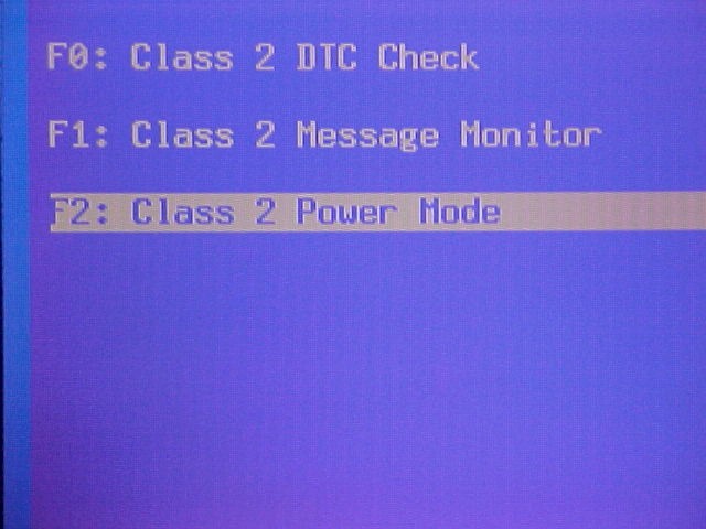
Recently a screen was added to the Tech 2 for checking the Power Mode operation. As seen in the picture below, you can access the Power Mode function by going to the Diagnostic Circuit Check and finding the new option for it.
Once you select this option the screen will then give you the status of the Power Mode.
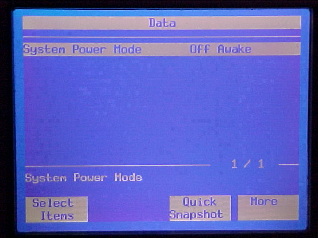 This screen shows that the ignition switch is in the off position but that the
Class 2 data bus has some modules that are still awake.
This screen shows that the ignition switch is in the off position but that the
Class 2 data bus has some modules that are still awake.
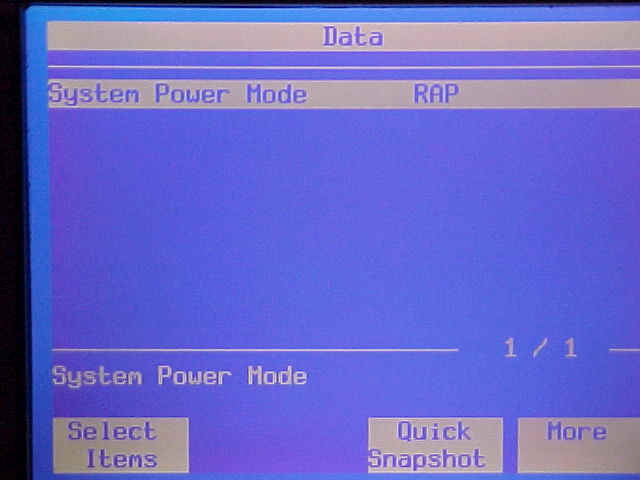
Once you turn the ignition to
the Accessory, Run or Crank position the System Power Mode message should change
along with it and indicate the proper mode. The only other mode you will get is
one for Retained Accessory Power.
This is a new feature of the Tech 2 starting
with software version number 21.007. If the vehicle are working on does not
respond correctly, then check the corresponding circuit from the ignition switch
to the Power Moding Master Module.
That's the latest on the Power Mode story, as developments occur we will add
them to this article.